Torsion Vibration Measurement and Analysis of Flue Gas Fan
 Torsion Vibration Measurement and Analysis of Flue Gas Fan
Torsion vibration can influence the operability and technical life of drive systems such as fan-motors or automatic trains. Typically, torsion vibration is weakly coupled (in the XYZ direction) with axial vibration when the drive system is straight. It can be nearly impossible to detect torsion vibration from axial vibration measurement because of this weak coupling.
This section discusses various ways to detect the presence of torsion vibration and how to quantify torsion vibration when troubleshooting.
The phrase torsion vibration refers to either the vibratory response or the vibratory source.
- Torsional vibration response
- The source of torsional vibration is dynamic torque fluctuation. Dynamic torque or torsion can be found using several methods, but is commonly found by measuring the difference of the angle across a section with known torsion stiffness.
Some ways to measure torsion vibration are to use:
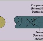
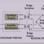
- A torque measurement unit, where strain gauges are used to determine the torsion angle. This is combined with knowledge of the torsion stiffness to find the the dynamic torque, as seen in Figure 1. This can be done using two encoders, two generators, etc.
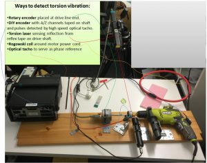
- A rotary encoder placed at a free shaft end or fitted with a wheel pressed to the shaft to detect the variation in rotation vibration, as seen in Figure 2.
- DIY encoder strips taped to the shaft, as seen in Figure 2. Such strips will always not quite match the joining section. However, it is possible to compensate for this error using postprocessing operations.
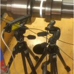
- A torsion laser using reflextape, where the difference between two laser beams is used to to determine torsion vibration, as seen in Figure 3.
The above is only a small sample of methods. More ways to measure are outlined here and here.
There are also signals that are proportional to torsion vibration. For example, we can measure the AC current in a motor or generator with Rogowski coils and use this measurement to determine the presence of torsion vibration and compare its strength between operational cases. This can serve as a “poor man’s” torsion vibration measurement system.
We can also use a three-phase motor or generator connected to the electric phases L1, L2, and L3. In addition, there is a ground (N) and a shield. Depending on the drive system, the electric cable can be straight through or coaxial shielded.
The simplest way to install a Rogowski coil is to do so during the electric phase (L1, L2, or L3), as seen in Figure 5(a). However, you can also install the Rogowski coil around the shielded cable and measure the summed current (L1+L2+L3+shield+ground), as seen in Figure 5(b). The latter setup is simple, can be installed while in operation, and works because the sum of the states (L1+L2+L3 ), which for steady state conditions equals zero, cannot be zero when there is an imbalance in the system, such as that from torsion.
(A)
(B)
(C)
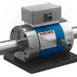
Figure 1. A & B) Torque measurement unit using strain gauges. Units like these can be calibrated, and are typical for permanent installations. For obvious reasons, they can be difficult to install while troubleshooting a machine. Also, a disadvantage is that this type of system usually relies on transfer of signals from the rotating shaft, though this is not necessary when encoders are used. Pictures from . C) Product example . (Click on picture to enlarge)
Figure 2. Use of one or more rotary encoder to detect torsion vibration. The encoder is placed at the free end. Note – in this example, the encoder is deliberately connected via a flexible shaft to cause a torsion resonance. A DIY encoder taped onto the rotating shaft can be used as well. Adjacent to the DIY encoder is also a small strip of reflex tape for use with a torsion laser. The use of DIY encoder strips and one or more TTL laser tacho switches allows both the AC and DC components of torque to be determined. Fixtures to keep the laser tacho aligned with the encoder strip are necessary for an accurate measurement. The errors in the encoder strip pattern can be compensated for by software. (Click on picture to enlarge)
Figure 3. Torsion laser (left) combined with optical tacho reference (right). The reflextape mounted to the drive shaft is seen as the shining band to the right of the torsion laser. The advantage of the laser is that it is easy to install—it can even be hand-held. The main disadvantages of the torsion laser are that it requires the shaft to be stopped in order for the reflex tape to be installed, and provides only the AC component of the torsion vibration, i.e. that the static torque cannot be determined from a measurement at two locations. (Click on picture to enlarge)
Figure 4. Use of Rogowski coils for the measurement of AC current. In this case, the coil was located around most of the power cables located between the Variable Speed Drive (VSD) and the Motor and therefore, detect the ‘Summed ‘(L1+L2+L3+ground) AC current. (Click on picture to enlarge)
(A)
(B)
(C)
(D)
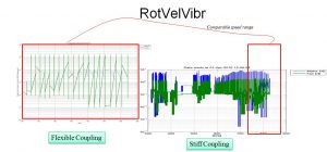
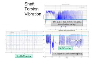
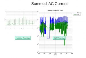
Figure 5. Example measurement on a flue gas fan with variable speed drive and fitted with a flexible and stiff coupling A) Set up using two lasers. B) rotation vibration velocity. C) Dynamic torque. D) Summed (L1+L2+L3+ground) AC current measured with Rogowski coil. (Click on picture to enlarge)
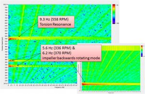
(A) Amplitude-RPM-Frequency map
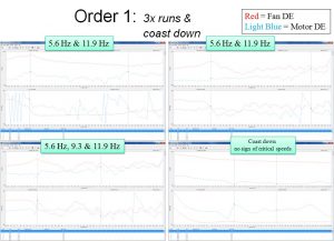
(B) Order FRFs from four different runs of the Flue Gas Fan
Figure 6. Speed up of flue gas fan with variable speed drive where an optical tacho serves as the reference. The presence of three critical speeds can be seen in the A) Amplitude-RPM-Frequency map and in B) the order FRFs. The critical speed at ~560 RPM is a torsion resonance, while the two other critical speeds are caused by backward rotating modes. (Click on picture to enlarge)


