

Slugging Pulsating Pressure Source Characteristic & Measurement
 Multiphase Slugging Pulsating Pressure Source Characteristic & Measurement
Slugging in multiphase flows can be caused by a variety of factors (see here and here ), including from pigging operations, operational conditions, where low flow velocity cause mixtures to separate (terrain-induced slugging), or low points where liquids at sufficiently high flow flood the low point cross section and cause periodic slugging (also known as riser slugging), as seen in Figure 1.
Periodic slugging can be detrimental to piping fatigue, as it causes large pressure pulsations in the system. Currently, the industry uses slugging simulators to reduce the occurrence of slugging, such as Leda Flow and Olga.
However, advanced field testing using multichannel measurement systems, state-of-the-art signal analysis, and externally applied pressure sensors can easily become part of normal operations and reveal complimentary insights, as well as be used for QA of the simulation model used for Flow Assurance. In addition, dynamic stress and pipe vibration can be measured and assessed for fatigue risk and relative motion across the flexible element.
This post will touch on a few of the things that can be gathered from such advanced field testing.

(A) Figure from reference.

(B) Picture from reference
Figure 1. Various types of slugging conditions. A) Terrain-induced slugging. B) Slugging at a low point introduced by flexible connection between a Christmas tree and platform piping. (Click on figure to enlarge)
In a way, the slugging aeroacoustic source mechanism is similar to that of a siren, as seen in Figure 2.

Figure 2. The acoustic siren. Picture and text is from the Smithsonian. A demonstration movie of the disk siren. Click on figure to enlarge)
The siren’s aeroacoustic source mechanism works by turning on/off the massflow— it is an acoustic monopole type. As exemplified in Figure 2, a siren can be built from one or two discs with matching holes. One disc remains stationary, while the other rotates and blocks/unblocks flow through the holes. In Figure 2, we have a single spinning disc, which does not generate as effective a sound as sirens with two discs.
From an aeroacoustic source point of view, turning the mass flow on and off is what slugging does as well. To elaborate, the slug momentarily blocks the flow until the pressure difference becomes large enough to accelerate or lift the slug from its low point.
The end result from turning mass flow on and off is pressure pulsation in the pipe system, which causes piping vibration and reduces the pipe’s fatigue life. Note that the slug may be created at a single position, but the pulsation will travel throughout the piping system at the speed of sound, which tends to be about one order of magnitude higher than the flow speed.
Furthermore, pulsation tends not to decay much due to internal damping, i.e. the conversion of pulsation into heat (a nearly irreversible mechanism). Pulsation amplitude reduction is primarily found at junctions and in large volume bottles where pulsation amplitude reduces as it is distributed over a larger cross-section. Hoses may add some pulsation damping when they are flexible and curved, as the hose material has significantly more structural damping and can vibrate when the pulsation occurs.
Pulsation can be measured using externally applied piezocables. In the case of a flexible hose causing a low point, two piezocables were applied directly on the hose outer casing, as seen in Figure 3. The upstream/downstream pressure pulsation (P1/P2, respectively) from pipes with and without periodic slugging is shown in Figure 4. As expected, we find minimal phase delay and amplitude difference between pulsation signals when slugging is not present, and significant phase delay and amplitude difference when slugging is present.

Figure 3. Piezocable installation on flexible for slugging measurement. (Click on figure to enlarge)

(A) Pulsation measured with production without of slugging. The time lag seen here is mostly due to the distance in separation between the piezocables, and the pressure variation is smooth and slow. The figure on the right is a close-up view of the figure on the left.

(B) Pulsation measured with production with slugging where we see short duration events take place. The right hand figure is a zoom in on the left hand figure.
Figure 4. Pulsation signals measured with the upstream (P1) and the downstream (P2) piezocable sensors. Scales and names have been removed. A) Without slugging. B) With slugging. (Click on figure to enlarge)
The piezocables use charge amplifiers to amplify the signal. The slowest event we can pick up with this setup would be a 10s long event (1/10 Hz), i.e. we will not be able to see the complete slugging event if the time between slug events is larger than 10 seconds.
With the hose cross-sectional area, S and, the difference between upstream (P1) and downstream pulsation (P2), we find that the SlugLoad = S*(P1- P2) = S*dP. The dP pulsation signal is shown in Figure 5.

(A) Without slugging. We see a slow, ~9s , pressure variation caused by flow variation.

(B) With slugging. We see sharp pulsation pressure spikes superposed on the slow pressure variation. We also find that this flow variation is less regular when slugging is present.
Figure 5. Example of the pulsation differential signal dP which is proportional to the slug load. Scales and names have been removed. A) Without slugging. B) With slugging. (Click on figure to enlarge)
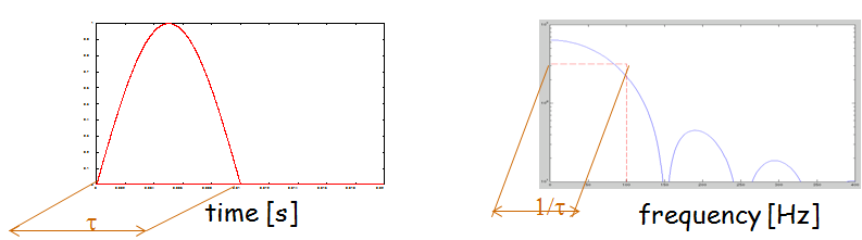
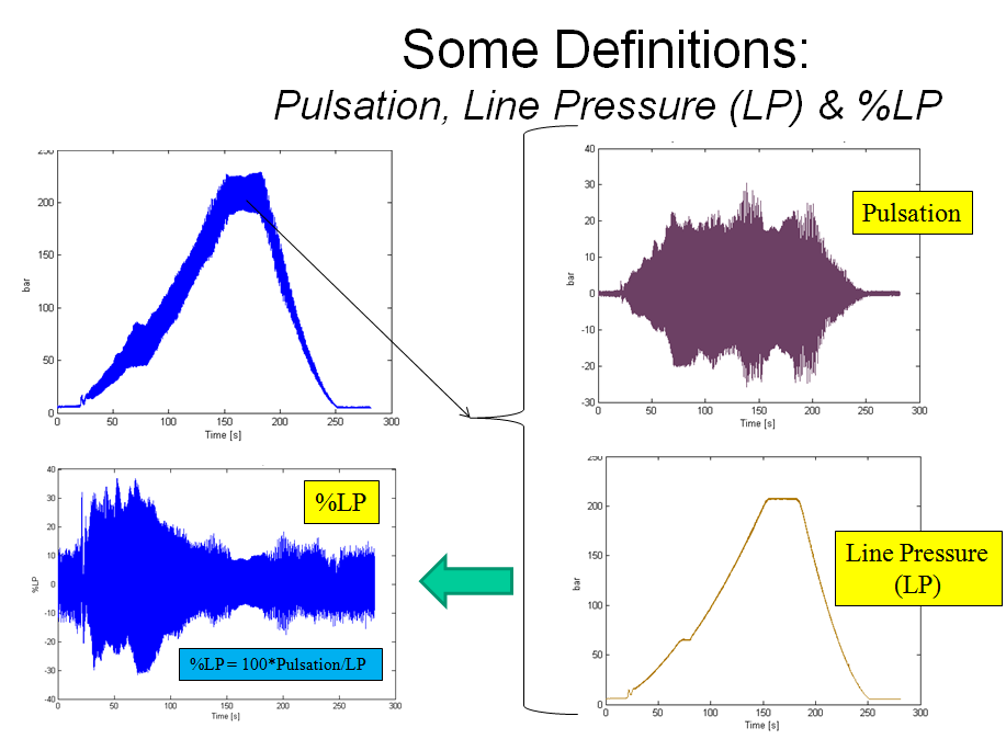
The rule of thumb for transient impulses of duration dt is that the spectral amplitude is constant up to a frequency of 1/ dt [Hz], and that 90% of the pulse energy is found below 2/ dt [Hz]. Slugging excitation is of wide band random character, as pulsation cannot be perfectly periodic (as, say, that of a rotating machine), and slugging pulses are not perfectly uniform. In other words, slugging should be expected to excite acoustic system modes and thereby affect the system %LP (= 100* Pulsation/LinePressure) .
Examining pulsation downstream to the system low point where slugging takes place, we find that pulsation wave propagation steepens and forms shock waves, as seen in Figure 6. Shock waves are important because they increase the peak pressure pulsation and thereby increase the fatigue stress range.

(A) Without slugging.

(B) With slugging. The spikes that can be seen in the right figure are shock waves generated by nonlinear wave steepening in the multiphase flow.
Figure 6. Pulsation measured downstream the flexible. A) Without slugging. B) With slugging. The shock waves caused by periodic slugging and wave steepening. (Click on figure to enlarge)
Note that a shock wave heavily depends on phase, as the wave peak lies in phase with the wave through when the shock wave exists. Shock waves easily collapse, such as when they are forced to turn a sharp corner to reach a pressure sensor. This insight implies that we may not be able to sense the shock wave with all our sensors. Therefore, depending on local geometry, places where shock waves can be expected to affect point loads are at interfaces directly exposed to an oncoming wave such as pipe bends, valves, and ruption disc interfaces.
Furthermore, the presence of the higher pulsation amplitudes associated with shock waves may offset the production system operating point and influence things like precipitation, flow conditions, etc.
With pulsation measurement, we can relate pulsation and slug load to production conditions such as flow rate, GOR (Gas Oil Ratio), etc. We observe that being able to quantify when slugging occurs, the slug load strength, and its spectral content and periodicity enables us to examine other properties of slugging and the effects of various slugging countermeasures.
Piezocable sensors can be used for pulsation measurement and associated data can be used to derive a variety of fluid properties, e.g. the amount of gas included in the fluid as well as the flow speed, i.e. it has the potential to act as a low cost multiphase flow sensor that is able to function at locations where flow is complicated.