Boiler pressure pulsation measurement
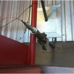
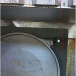
 A boiler (pressure) pulsation measurement can be made directly by using piezoelectric pressure transducers that are installed into the boiler wall, as seen in Figure 1. Boiler pulsation can also be picked up indirectly using accelerometers placed on the boiler wall, though this setup is limited when compared with the use of pressure transducers, as seen in Figure 2.
Comparing the boiler pulsation measurements to known boiler data such as power, gas flow velocity, and so on allows for the assessment of root cause problems such a Vortex Induced Vibration (VIV) on heat exchanger pipes, acoustic cross section standing waves, deep cavity pulsation, thermoacoustic excitation, and so on.
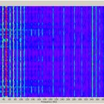
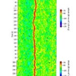
For VIV, the relation between the vibrating frequency( f [Hz]), flow velocity (U [m/s]), and flow across a heat exchanger pipe of diameter d [m], is f = 0.2U/d. The heat exchanger tubes are bundled with uniform separation which cause harmonics to arise, as seen in Figure 3 and Figure 4.
Noise and vibration outside of a boiler is not always caused by pressure fluctuation inside the boiler and may be caused by other machinery. These alternate causes can be assessed using transfer functions and coherence.
Figure 1. A pressure transducer installed for boiler internal pressure pulsation measurement. (Click on Figure to enlarge)
Figure 2. An accelerometer placed on the boiler wall. (Click on Figure to enlarge)
Figure 3. We see that the boiler pulsation frequency varies with time— in this case through the boiler flow. (Click on Figure to enlarge)
Figure 4. Example Time-Frequency-Amplitude spectrogram showing harmonics that arise from flow across a heatexchanger tube bundle. We see that response (i.e. amplitude shifts from green to yellow to red for the ~38 Hz component) increases when the VIV frequency coincides with, e.g. acoustic cross section resonance or with mechanical tube resonance. (Click on Figure to enlarge)


