Designed Damping
 Damping design
Many people confuse damping with amplitude reduction. To clarify and define, damping is a process in which vibration energy is converted into heat.
This conversion process is nearly perfectly irreversible. In other words, we rid ourselves of vibration energy that is converted into heat.
The vibration made when a pipe steel structure is impacted by a hammer blow, as sensed by a triaxial accelerometer, can be heard here:
The vibration of the same steel structure with damping added can be heard here:
The difference in damping between the two cases is that the latter has 10x more damping. The top example has a level of damping that is typical for pipework. The lower example has structure damping that was designed into the structure.
Damping is important only at and near resonance, as the effect from inertia and stiffness cancel at resonance (why?). It logically follows that response at resonance is inversely proportional to damping at resonance, i.e. system response at resonance depends on the strength of the excitation and the damping value.
Natural processes that create damping ‘for free’ are:
- Friction
- Viscous, e.g. squeeze film damping
- Transmission
- Non-linear mechanisms
Friction and viscous damping can arise between component interfaces and/or be internal to materials.
Transmission implies that a vibrating object is coupled with other objects and sends vibration energy into these. If the receiving object is sufficiently large, this transmitted power is converted to heat by various damping processes. Transmission in this context means sound radiation, pulsation and structure-borne sound. Transmission damping usually is stronger at low frequency than at high frequency.
Examples of non-linear mechanisms include rattling, interaction or non-linear stiffening/weakening. Such mechanisms create pseudo-damping, which is not a direct conversion into energy but a system behavior that resembles the effect of a true damping process.
Rattling implies that some of the system energy is vibrated off when part of the system mass unloads from the vibrating system. This energy either completely leaves or may return as an impact at a later time. One example of this is so-called beanbag, dampers where small balls are thrown into the air in a bag. When acceleration exceeds 1 g , it impacts back on the vibrating object, as well as on other balls in the bag. The impact distributes the energy of the ‘bean’ across a wide set of frequencies.
Interaction between flow velocity and vibration velocity can lead to either damping or excitation (so-called negative damping).
Non-linear stiffening/weakening implies that a resonance is more difficult to find in conditions where it can accumulate vibration energy, as the system’s natural frequency respectively increases/ decreases when vibration energy, and hence load, increases in the system.
Damping can be expressed using various descriptions that all relate to different physical mechanisms. Most damping models, unfortunately, are rather simple models of the real physical process that is involved. The most common damping models that are used in dynamics are:
- Absorption coefficients
- Structural damping, which describes material internal friction.
- Viscous damping, which describes dashpot damping and, to some extent, sound radiation.
- Rayleigh damping, which is used for mathematical convenience and lacks physical motivation. Rayleigh damping provides a damping effect that varies with frequency, and this variation depends on how it is defined.
The definition of damping types can be found here: Link
Absorption coefficients are found from the reverberation of time measurement in test rooms or ordinary rooms. The absorption coefficient describes damping as a property of the absorber surface. This is an obvious simplification. Absorption factors found in one room configuration do not necessarily describe damping in another room with significantly different dimension proportions.
Friction damping works only when friction is overcome so that relative motion arises between loaded interfaces. More simply put, friction damping does not work at low vibration amplitudes and is amplitude-dependent, as the damping force does not grow once friction is overcome.
Viscous damping varies with temperature, as the kinetic viscosity is viscosity divided by material density and density varies with temperature.
The damping process can be strong or weak. One definition of critical damping is where a freely-vibrating sdof system undergoes exactly one period before coming to rest. Lighter damping is referred to as under-critic and stronger damping is called over-critic.
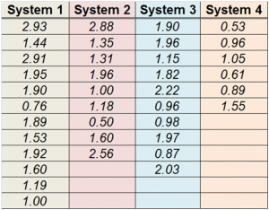
Table 1 below shows loss factors (%of critical) for four pipe systems of similar design that are close to each other. As can be seen, there is a large variation in damping factors; a factor of 6x is observed.
Table 1. Table of damping values for the fundamental modes found in Experimental Modal Analysis of four pipe systems of similar dimensions with identical functions that are situated next to each other. As can be seen, there is a 6-factor difference between the smallest and highest damping values. (Click on table to expand)
The above implies that damping that is handed out ‘for free’ and is not very reliable. One way to reduce design risk for dynamic analysis, therefore, is to actively plan damping into a design.
Damping that is added must be stronger than the background damping. To exemplify, for a damper truly to show imapact on all modes in System 1 of Table 1, it must exceed 3% of critical. A damping increase to 6% would half the response of mode 1 (2.93%) and cut response by a six-factor for mode 12 (1%).
Examples of damping design elements are:
- Damping material
- Damper elements
- Gas/hydraulic dampers, where damping is caused by pressing a gas/liquid across a pressure drop. (Link)
- Viscous dampers, e.g. Gerb viscodampers, where damping comes from material relaxation when the damping material is sheared. (Link)
- Damper links where a viscoelastic damping layer is loaded in shear (Link)
There is one more common damper type, the tuned dampers, where a mass-spring system is used to add damping and/or apply a counterforce. A tuned damper differs from the above mentioned demper types in that its effect is localised to a single frequency (per dof, in theory a maximum of six, but most often just one) (Link)
It is often believed that adding damping is a question of material selection. It is true that material selection matters, but a more apt description is material application.
Imagine that you buy the world’s best damping material. Of course, it will not work if it is not loaded – it would be like buying a damper for your car and believing it will help when it is still in its original packaging. Similarly, making a car entirely from, say, rubber is no guarantee for high damping.
Active damping design requires an understanding of the damping processes that are involved, as well as actively designing how the damper should be loaded to work properly.
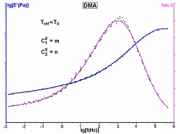
Finally, the material properties of viscoelastic damping materials vary greatly with temperature and frequency, Figure 1. Temperature dependence is typical for most damping mechanisms. If they are not temperature-dependent, damping typically depends on vibration amplitude or a mix of temperature/amplitude.
Figure 1. Master curve for viscoelastic material. The blue curve shows the Young’s modulus as it modifies from the rubbery region (left, -3 lg(f(Hz)) to the plastic region (right, 6 lg(f(Hz)). The Young’s modulus typically changes ~1E3 times in magnitude between these regions. The magenta curve shows the structural loss factor, which peaks where the Young’s modulus gradient is the largest. (picture from)


