Reciprocating Pumps Pulsation Signature
 Reciprocating pumps emit strong pulsation when there is no pulsation countermeasure. Reducing pulsation saves not only pump wear but also piping fatigue life.
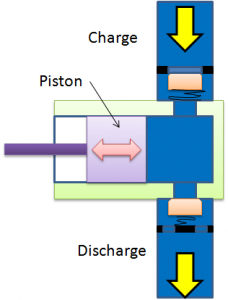
Reciprocating pumps use a reciprocating piston to displace fluid volume. Inlet flow is controlled by a passive valve, i.e. a springloaded valve that opens when the piston expands the cylinder’s volume (see Figure 1). The discharge valve is closed during the suction stroke. The discharge valve is opened when the piston decreases the cylinder’s volume.The suction valve is closed during this compression stroke.
(A)
(B)
Figure 1. A) The principle of a reciprocating pump. B) Animation example for reciprocating pump. (Click figure to start animation)
As liquids are nearly incompressible and reciprocating pumps tend to run at slow speeds, in theory, the valves should open/close as soon as the suction/discharge stroke begins. In reality, liquids contain some gas and therefore, exhibit a degree of compressibility, which introduces a valve delay.
In addition, the valves are pre-tensioned by the use of a spring. This implies that cylinder pressure must overcome a certain value before the valve opens. Again, compressibility affects pump operation and causes a valve delay. Such delays can be controlled during pump design when balancing valve design variables such as valve weight, spring stiffness, pre-loading, and valve lift.
It is obvious that the design is affected by pulsation, as the differential pressure across the valve controls its opening/closing action. When pulsation becomes significant, i.e. a high LP percentage, valve opening/closing can become controlled by pulsation. In such situations, one may encounter situations where so-called ‘back flow’ arises in multi-cylinder pumps. Back flow is when flow is discharged from one cylinder into an adjacent cylinder rather than being fully ejected with the discharge flow.
High LP percentage situations tend to control valve operation and, as a result, valves tend to open/close more frequently than intended. This implies that valves must move much faster to handle the flow and, consequently, valve impacts become stronger and more frequent. Therefore, valve wear tends to increase in this kind of situation, worn valves emit stronger pulsation, which may lead to equipment damage. Strong pulsation also tends to increase the pipe system fatigue load.
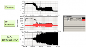
Reciprocating pumps tend to emit strong pulsation, particularly when there is no pulsation countermeasure (see Figure 2).
Figure 2. Triplex pumps operating without pulsation countermeasure on the discharge side can be seen to cause strong pulsation. We see that pulsation tends to be stronger in conditions where LP is dropping. In the example, this is due to the pump system’s increased flow rate. (Click figure to expand)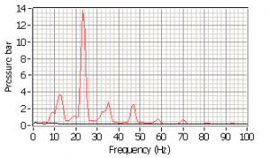
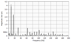
Figure 3. Top- Triplex pump without countermeasure on discharge side. Bottom – Triplex pump (different size and manufacturer) fitted with a bladder on its discharge side. We can see from the autospectrum that the bottom pump example has a smoother operation, as its fundamental (3rd Order) component is stronger than other pump orders, while the top example shows a dominant 6th pump order. A Triplex pump should have 3rd and 6th pump Orders of similar strength. The top figure example is likely a situation where pulsation affects pump operation. (Click figure to expand)
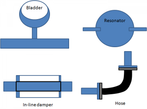
Pulsation can be mitigated using:
- Bladders
- In-line dampers
- Resonators
- Hoses
Figure 4. Types of pulsation countermeasures.
The above countermeasures should be applied both on the pump suction and discharge sides, as a pump uses passive valves, or valves that open and close depending on the relative pressure inside or outside the cylinder. Pulsation may affect when and how valves open and valve opening characteristics in turn affect pulsation strength. Therefore, low pulsation is favored for smooth pump operation.
The acoustic principle involved in the above-listed countermeasures is to create a discontinuity that reflects an impinging wave back to its source. When the countermeasure is placed close to its source, usually physically close to the pump charge or discharge sides, the reflected wave bounces back and cancels the outgoing (emitted) wave. This interaction reduces the pump’s acoustic source strength. This tends to result in lower pulsation and, consequently, a longer valve, more piping (treating iron) and better pump life/reduced maintenance costs.
The bladder causes a discontinuity by using a gas volume. This gas volume changes with Line Pressure. Doubling the pressure halves the bladder gas volume, which affects its efficiency. Bladders therefore tend to be ‘pre-charged.’ For example, if the pump is expected to operate at 100 bar, the bladder would be pre-charged to, say, 90 bar. This implies that the bladder would press down on its inlet and simply would not work at Line Pressures below 90 bar. It would still do a poor job at 90 bar if pulsation is large enough to get it to open and close and, in fact, it may even increase pulsation during such (malfunctioning) conditions.
Raising the Line Pressure to 100 bar would allow about +/-10 bar pulsation. In order to be used successfully, bladders therefore tend to need to be ‘tuned’ to actual conditions and one needs a basic understanding of the job the bladder is tasked to do. Therefore, it is easier to control pulsation when a reciprocating pump operates a long time at nearly constant Line Pressure and for suction pressure, which tends to be tightly controlled.
In-line dampers tend to work for lower Line Pressure and are usually applied on a reciprocating pump’s charge side. Bladders can be used on both the suction and charge sides.
Hoses and resonators tend to work regardless of Line Pressure. Both countermeasures are the most effective at high frequency. A resonator that involves a very large area of cross section change can reduce pulsation from low to high frequency at any Line Pressure.


