What is Angle- and Order- Analysis?
 When analysing rotating machinery, one may use time or rotation as the reference.
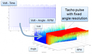
A time signal can be resampled from a fixed time resolution, dt, to a fixed angle resolution with the help of the tacho signal. This is what the tacho pulse looks like when resampled from the time domain to a fixed angle resolution (see Figure 1):
Figure 1. A tachometer signal resampled from the time domain to the angle domain. One revolution is one square pulse period. The machine is speeding up, as can be seen in the square pulse width being shortened in the time record. (Click figure to enlarge)
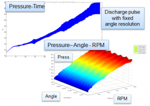
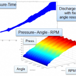
When resampling a pressure signal, one can see a pulse at each rotation. This is what the pressure pulse looks like before and after resampling from the time domain to the angle domain (See Figure 2):
Figure 2. Using the information found in Figure 1, we can resample also other signals from the time to the angle domain. The example here shows pulsation emitted from a pump. Both subfigures contain exactly the same data. The pressure-RPM-angle view simplifies machine signature analysis, as we can see at which angle each pressure pulse was emitted by the machine. (Click figure to enlarge)
Some information that can be gleaned from the above picture is whether the machine has discharge pulses that are evenly distributed between the cylinders and if the discharge pulses are emitted at a correct angle.
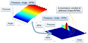
Using rotation as a reference, a value of 0.5 implies that half a revolution is completed. By taking a FFT of the rotation signal, we can get the Order spectrum. Taking order spectrum as a function of machine speed, we can create a Campbell diagram for machine orders (see Figure 3):
Figure 3. Data is shown as (0-360 degree) angle, but is in the analysis (0 – 1) revolution. Taking a Fast Fourier Transform (FFT) of the angle domain signal yields the order spectrum. (Click figure to enlarge)
In the above Pressure-Order-RPM figure, we can see that Order 12 excites a system resonance and that the discharge pressure oscillates. If this pressure oscillation is a fair portion of the average pressure, i.e. the line pressure, it will cause a varying back pressure that will affect when the passive pump valves open and close.
If Order 1 implies actions that arise once per rotation, Order N implies actions that arise N times per rotation. For example, a four-stroke engine will experience one explosion per two rotations per cylinder. The explosion is 0,5 order per cylinder and, thus, a 4 cylinder engine will have a (0.5*4 =) 2nd Order firing frequency. A pump emits one pulse per two strokes and therefore a N cylinder pump has an Nth order ‘firing frequency.’
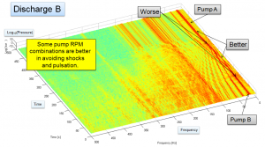
To gain Order resolution 1/N requires a record length of N revolutions. This implies that we suppress short duration information and focus on machine specific information. Therefore, Order analysis yields ‘slow’ information on the machine. Using time as the reference is better when short duration events matter (see Figure 4):
Figure 4. Example of Ramp Up/Ramp Down of two pumps in search of optimimum operation. We use fixed time resolution and FFT to generate the plot. Machine Orders are the red lines that end at fixed frequencies. Shocks appear across the frequency axis at the time they arise. Two shocks are indicated in the figure by the ‘Worse’ arrows. (Click figure to enlarge)


