Low Frequency Sound Transmission into Offshore Cabin
The strongest helicopter noise is found at frequencies below 100 Hz. Helicopter landing and take off at platforms can cause sleep disturbances.
Offshore space is premium. Cabins therefore tend to be compact. Cabins are also module-built and installed side-by-side, which leads to complicated acoustic interrelation regarding flanking transmission paths.
To further compound the issue, a platform is very stiff compared to an ordinary building on land. Many of the truths known in building acoustics, therefore, do not hold. At low frequency, stiffness is the governing factor for sound transmission via the platform bulkheads. This makes the wall design process suitable for fully coupled Finite Element analysis.
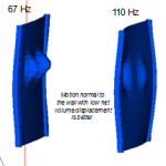
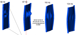
Examples of bulkhead vibration shapes (excerpt from a larger fully coupled FE model) show distinct shapes that transmit sound (see Figure 1):
Figure 1. Bulkhead and window vibration patterns at frequencies with a high sound transmission. (Click figure to expand)
Here are some animations of a vibroacoustic test made in a mockup of the same cabin (see Figure 2). About 900 FRFs were used for this animation and the steel wall vibration was excited by an acoustic point source located at the head position in the cabin. Qring had to settle for wall vibration measurements as the outside acoustic environment was far too noisy at all times for acoustic measurements.
A reciprocal measurement would be to place the sound source outside of the cabin mockup and measure instead the sound inside the cabin. This approach was tested and failed to recognise differences between walls due to flanking transmission paths.
Figure 2. Measured vibration where a reciprocity loudspeaker was placed at the head rest position in the bed. Sound radiation from wall and window vibration was computed using Rayleigh integration. This procedure allowed estimation of the panel contributions and a discrimination between wall and window types. (Click figure to start animation)
The computed FE shape and mockup wall vibration do not match, as different windows were used and as the FE structure model and the physical mockup did not have identical traits. Nevertheless, some of the core elements for the sound transmission can be identified both in the FE model and the test.
Along with pinpointing actual acoustic transmission problems, the measured vibrations were used to predict the panel contribution from the wall so that flanking paths and the contribution from windows could be assessed.


