

Pulsation Measurement
Correctly measuring pulsation is more difficult than it seems.
As mentioned elsewhere (Link),
Pressure = LinePressure + Kinetic Pressure + Pulsation.
Line Pressure (LP) usually is measured without much problem. LP can be affected by Pulsation when long tubing leads to the pressure sensor (see Figure 1).
Industry-type pressure sensors tend to be placed on a small bore fitting, often with a blocking valve situated between the pressure sensor and the flange (see Figure 1- flange not shown). This setup works for Line Pressure and suppresses Kinetic Pressure, but is less ideal for pulsation measurement, particularly for liquids.
Figure 1 shows three sensor orientations: 12:00, 15:00, and 18:00, respectively.
- The 12:00 position is typical for industry piping and has the benefit of also allowing the use of the small bore for venting. A problem with respect to pulsation measurement is that industry-type fluids tend to involve gaseous bubbles that tend to collect in front of the pressure sensor membrane. The end result is an acoustic low pass filter that ‘cushion’s’ impinging waves and suppresses the correct registration of fast pressure oscillations, i.e. pulsation.
- The 18:00 position has the obvious drawback of accumulating debris and dirt. This orientation is therefore uncommon for pressure sensors and is mostly used for drains.
- The 15:00 position is the better choice for pulsation. Ideally, it should be at 15:15 or 20:45 so that gas does not build up in the pipe.

Figure 1. Pressure sensor orientation and mounting styles. The 15:00 position and arrangement is preferred for industry-type pulsation measurement.
For pulsation to be correctly measured, the pressure sensor must be firmly attached to the pipe. Vibration and local flexing, e.g. in sensor threading, will otherwise affect the pulsation measurement.
Another problem with the pressure sensor configuration shown above is that the pipe that leads up to the sensor that may contain local acoustic resonance. This arrangement can greatly amplify pulsation readings at resonance frequencies where there is a L = (2n+1)·λ/4= (2n+1)·c/(4·f) resonance in the tube. The error is 1 dB (12%), and less at frequencies below 1/3 of the first acoustic resonance frequency in the pipe in front of the pressure sensor. This is the above mentioned ‘long tubing’ problem (see Figure 1) that may affect LP.
The best pressure sensor arrangement is shown in Figure 2. The sensor is aligned parallel to the flow to suppress influence from Kinetic Pressure. The probe should not be flush mounted to the wall in order to avoid higher reading produced by boundary layer pressure, but it should penetrate this- and the thermal boundary layer. Usually, this translates to the gage penetrating into the flow by 10mm to 20mm. The distance that is required to penetrate these layers can be calculated.
Figure 2. Ideal pressure sensor mounting.
Externally applied sensors can be used in case a pressure sensor simply is not available, as can be seen in Figure 3 and Figure 4. Pressure is implicitly derived from the pipe cross section ring mode stiffness.
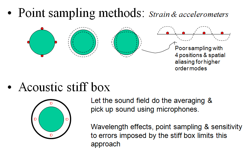
A common technique is to use a full bridge of strain gauges to detect the pipe cross section breathing motion. Resistive strain gauges would then be placed at 12, 15, 18 and 21 o’clock positions, i.e. 90 degrees apart. Our experience is that a full bridge works better than the use of four accelerometers as accelerometer signals must be integrated to detect displacement and as accelerometers are more prone to pick up local deformation.
As shown in Figure 3(a), point sampling methods suffer from the fact that they will inevitably be affected by pipe wall bending. A more mathematical take on the situation is that point sampling methods attempt to integrate the measured pipe wall vibration into a value that should be zero for all modes except the pipe section ring mode (radial expansion/contraction).
This procedure is very sensitive to errors for the pipe cross section modes it stands a chance at preventing but cannot prevent many other types of pipe cross section modes. Application therefore is limited to low frequency where pipe cross section modes do not exist.
Another (better) version is the use of an acoustic stiff box where an acoustic volume is used to make this integration, Figure 3(b). This approach is limited in frequency when integration is affected by acoustic modes in the cavity. Replacing the cavity air by helium is a trick to shift this problem to higher frequency.
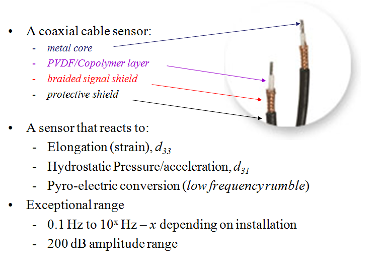
The approach preferred at Qring is to use Piezocables for the pulsation measurement. This type of sensor has a very wide frequency range and an exemplary dynamic range.
The Piezo cable’s main limitation is its temperature range. For PVDF and copolymer, the highest temperature for optimum performance is below 60 C, after which the cable starts to age and change its sensitivity. There are ways to compensate for this and Piezocables can be used up to about 150 C.
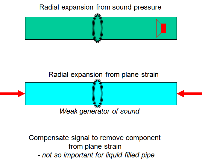
The line sampling approach must consider in-plane mechanical stress that also produces radial expansion/contraction. Reducing this stress component is more important for stiff pipes (=steel) and weak ‘fluids’ (=gas) than it is for weak pipes (=plastic) and stiff ‘fluids’ (=water).
(A)
(B)
Figure 3. Different types of externally applied sensors for implicit pulsation measurement. A) Point sampling methods using accelerometers, strain gauges or microphones. B) A line sampling method using a Piezocable provides a sensor that is orthogonal to pipe wall bending and only reacts to the pipe cross section ring mode. (Click figure to expand)
Figure 4. How a Piezocable is built up.(Click figure to expand)