

Emergency Generators
 Reserve power, e.g. emergency diesel generators, are not units intended for continuous operation, but rather systems tasked with vital safety functions. To ensure this system safety function, these systems are tested for a specified period of time at regular time intervals; say, a few hours every two weeks.
A common problem for these types of units is that their heaviest components, the motor and the generator, rest on weak skids and frames. Industry-sized generators emit a fair amount of structure-borne noise and can become a potential noise source when located near offices and living quarters. Vibration isolation is introduced to remedy structure-borne noise and, in some cases, introduced to provide seismic protection.
Types of setups we have come across are shown in Figure 1.
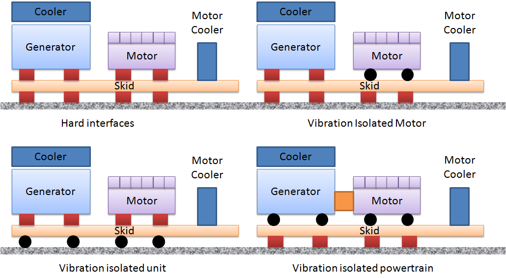
Figure 1. Different types of genset configurations. Red blocks signify hard connections. Black blobs signify vibration-isolated interfaces. The drive shaft connection between the motor and the generator tends to be a flexible coupling and is not shown in the figure.
Industry-sized motors and generators are heavy objects and the skids tend to be open beam frames, often made of little more than IPE type beam sections. The combination of a weak skid and stiff and heavy objects with a centre of gravity located high above the skid beam bending neutral plane makes it a challenging task to create a low vibration setup.
The setup with the largest inherent stiffness is the setup that uses the stiffness of the floor, i.e. the bolted down setup shown in the top left of Figure 1. It tends to be also a good setup with respect to machine reliability. Unfortunately, this setup emits structure-borne noise and is exposed to seismic loads. When placed on a ship, FPSO or platform, it is also exposed to constraint force when the deck is moving from environmental loads. Such constraint force may affect machine wear.
It logically follows that the vibration-isolated motor setup is less prone to dynamic problems, as only the motor is vibration-isolated, but it may still emit structure-borne noise from the generator.
The two setups shown at the lower left and the lower right in Figure 1 show a higher potential for vibration isolation, but require a much higher degree of design to be successful.
The vibration-isolated powertrain, shown in the lower right section of Figure 1, is typical for smaller emergency diesel units where the generator is simply bolted directly to the motor. This kind of setup effectively recycles the emitted motor torque back to the engine block, as bolting the units together provides a torsion stiff path.
For large industrial units, an adapter unit is introduced. To design an adapter that is stiff in bending is difficult and, therefore, design tends to be restricted to the cycling of motor torque through the adapter. As both the motor and the generator are vibration-isolated, care must be taken to provide sufficient damping (= conversion of vibration energy into heat) in the vibration isolators, or the unit may face high vibration as the motor emits unbalanced force/moment loads.
The setup shown in the lower left corner of Figure 1 cycles motor torque back to the motor via the frame. In doing so, the frame is twisted and dynamic misalignment may be introduced if the frame is not sufficiently stiff.
The motor and the generator components tend to be fairly stiff and heavy. As a result, they do not vibrate very much.
However, for the units to function, there must be piping for cooling and lubrication distributed across the units. Such distribution can be done in many ways and often tend to be a problem source with respect to unit reliability.
The problem lies in the fact that for industry-sized units, it is very difficult to build a skid that is sufficiently stiff to introduce only minimal amounts of relative motion between the skid, motor, generator and the coolers. Connecting a hard pipe between two heavy units that each vibrate in different directions is similar to exposing the pipe to base vibration (as is the case for earthquakes). Also, the pipe has little weight and stiffness as compared to the motor and the generator.
As a result, piping tends to vibrate a lot and become highly loaded. The end result can be leaks, fretting and fatigue cracks in piping and support lugs. The practical remedy is usually to replace hard piping with flexible hoses.
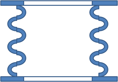
Another common problem source is the fact that the motor emits exhaust. The exhaust system tends to be a heavy unit as well for industry-sized generators. As the motor vibrates, it is connected to the exhaust system – which tends to be connected to the building/platform – via an exhaust bellow, Figure 2.
Figure 2. Principle of an exhaust bellow. The bellow is made 100% from metal. It flexes in its length direction. In its torque direction, it is as stiff as an ordinary straight pipe.
An exhaust bellow flexes in its compression direction, but tends to be stiff in its lateral directions and very stiff in its torsional direction. As a result, one should either make sure that the exhaust system is flexibly suspended and is able to follow the motor motion, or introduce more than a single exhaust bellow oriented in three independent directions.
Lastly, it should be mentioned that heavy industry-sized units require special consideration in their location. When placed on the ground, the rule of thumb is to place the units on a stiff and heavy block. Offshore, the deck beams must integrate and reinforce the unit support positions or interaction modes may arise where the deck acts as a local spring.